Node.js 带 WebSocket 的 Raspberry Pi RGB LED
使用脉宽调制
在前面的章节中我们学习了如何使用WebSocket,以及如何使用GPIO来打开和关闭LED。
在这一章中,我们将使用 RGB LED 和 PWM(脉宽调制)来根据用户通过 WebSocket 输入的输入显示不同的颜色。
RGB LED 是具有 3 种不同颜色的 LED。它具有红色、绿色和蓝色 LED (RGB LED)。
使用 PWM,我们可以设置 3 个 LED 的单独强度。这将允许我们混合它们,设置颜色。
我们需要什么?
在本章中,我们将创建一个示例,通过 WebSocket 使用网页控制 RGB LED。
为此,您需要:
- 具有 Raspian、互联网、SSH、安装了 Node.js 的 Raspberry Pi
- 这个Pigpio模块对于 Node.js
- 这个socket.io模块对于 Node.js
- 1×面包板
- 3×220欧姆电阻
- 1×RGB LED(共阳极或共阴极)
- 4×母对公跳线
单击上面列表中的链接以获取不同组件的说明。
笔记:您需要的电阻器可能与我们使用的不同,具体取决于您使用的 LED 类型。大多数小型 LED 仅需要一个小电阻,大约 200-500 欧姆。通常使用的具体值并不重要,但电阻值越小,LED 就会越亮。
安装pigpio模块
之前,我们使用了 "onoff" 模块,它非常适合打开和关闭。现在我们想要设置 LED 的强度,因此我们需要一个具有更多功能的 GPIO 模块。
我们将使用 "pigpio" Node.js 模块,因为它允许 PWM。
通过 PWM,我们可以将 LED 的强度设置为 0 到 255。
"pigpio" Node.js 模块基于 Pigpio C 库。
如果您使用的是 "Lite" 版本的 Raspbian,则很可能不包含此版本,必须手动安装。
更新您的系统软件包列表:
pi@w3demopi:~ $ sudo apt-get update
安装 Pigpio C 库:
pi@w3demopi:~ $ sudo apt-get install pigpio
现在我们可以使用 npm 安装 "pigpio" Node.js 模块:
pi@w3demopi:~ $ npm install pigpio
现在 "pigpio" 模块应该已安装,我们可以使用它与 Raspberry Pi 的 GPIO 进行交互。
笔记:由于 "pigpio" 模块使用 Pigpio C 库,因此需要 root/sudo 权限才能访问硬件外设(如 GPIO)。
构建电路
现在是时候在我们的面包板上构建电路了。
如果您不熟悉电子产品,我们建议您关闭 Raspberry Pi 的电源。并使用防静电垫或接地带以避免损坏。
使用以下命令正确关闭 Raspberry Pi:
pi@w3demopi:~ $ sudo shutdown -h now
当 Raspberry Pi 上的 LED 停止闪烁后,从 Raspberry Pi 上拔下电源插头(或关闭其连接的电源板)。
仅拔掉插头而不正确关闭可能会导致存储卡损坏。
在构建此电路时,重要的是要知道您是否有共阳极或共阴极 RGB LED:
您可以咨询您的提供商,或自行测试:
将电缆连接至 GND 和 3.3V 引脚。将 GND 连接到 RGB LED 的最长引脚,将 3.3 V 连接到任何其他引脚。如果它亮起,则说明您的 RGB LED 具有共阴极。如果没有,它有一个公共阳极。
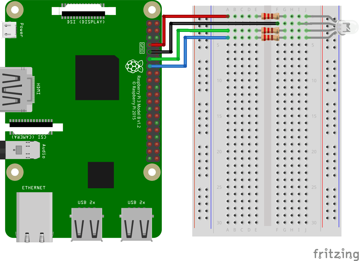
看上面的电路图。
- 在面包板上,将 RGB LED 连接到右侧接地总线列,并确保每条腿连接到不同的行。最长的引脚是共阴极引脚。在此示例中,我们将 LED 连接到第 1-4 行,共阴极引脚连接到第 2 行第 I 列。红色的腿连接到第 1 行 J 列,绿色的腿连接到第 3 行 J 列,并且蓝色的腿连接到第 4 行 J 列
- 在 Raspberry Pi 上,将第一条跳线的母腿连接到地面。您可以使用任何接地别针。在此示例中,我们使用物理引脚 9 (接地,第 5 行,左列)
- 在面包板上,将第一根跳线的公腿连接到与公共阴极连接的右侧接地总线列的同一行。在此示例中,我们将其连接到第 2 行 F 列
- 在 Raspberry Pi 上,将第二条跳线的母腿连接到通用输入输出接口别针。我们将用它来红色的腿,在此示例中,我们使用物理引脚 7(通用输入输出口4,第 4 行,左列)
- 在面包板上,将第二条跳线的公腿连接到左侧接地总线,与红色的LED 的引脚已连接。在此示例中,我们将其连接到第 1 行 A 列
- 在面包板上,在具有以下行的左右接地总线列之间连接一个电阻器红色的LED 的腿。在此示例中,我们将其附加到第 1 行、E 列和 F 列
- 在 Raspberry Pi 上,将第三条跳线的母腿连接到通用输入输出接口别针。我们将用它来绿色的腿,在此示例中,我们使用物理引脚 11(通用输入输出口17,第 6 行,左列)
- 在面包板上,将第三条跳线的公腿连接到左侧接地总线,与绿色的LED 的引脚已连接。在此示例中,我们将其连接到第 3 行 A 列
- 在面包板上,在具有以下行的左右接地总线列之间连接一个电阻器绿色的LED 的腿。在此示例中,我们将其附加到第 3 行、E 列和 F 列
- 在 Raspberry Pi 上,将第四条跳线的母腿连接到通用输入输出接口别针。我们将用它来蓝色的腿,在此示例中,我们使用物理引脚 13(通用输入输出口27,第 7 行,左列)
- 在面包板上,将第四根跳线的公腿连接到左侧接地总线,与蓝色的LED 的引脚已连接。在此示例中,我们将其连接到第 4 行 A 列
- 在面包板上,在具有以下行的左右接地总线列之间连接一个电阻器蓝色的LED 的腿。在此示例中,我们将其附加到第 4 行、E 列和 F 列
您的电路现在应该已经完成,并且您的连接应该与上图非常相似。
现在是时候启动 Raspberry Pi 并编写 Node.js 脚本与其交互了。
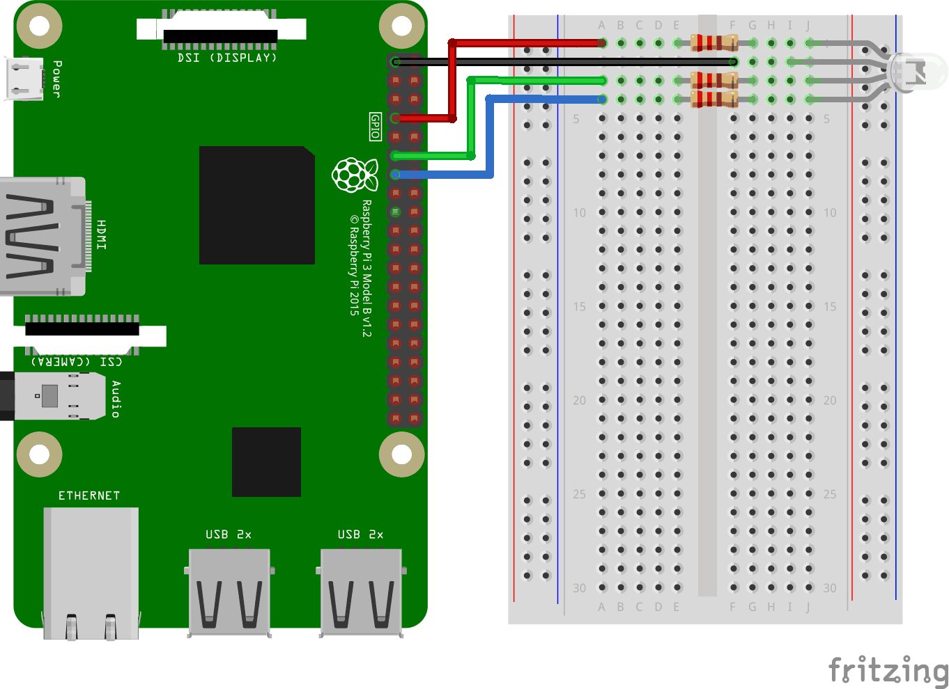
看上面的电路图。
- 在面包板上,将 RGB LED 连接到右侧接地总线列,并确保每条腿连接到不同的行。最长的腿是共阳极腿。在此示例中,我们将 LED 连接到第 1-4 行,共阴极引脚连接到第 2 行第 I 列。红色的腿连接到第 1 行 J 列,绿色的腿连接到第 3 行 J 列,并且蓝色的腿连接到第 4 行 J 列
- 在 Raspberry Pi 上,将第一条跳线的母腿连接到通用输入输出接口别针。我们将用它来红色的腿,在此示例中,我们使用物理引脚 7(通用输入输出口4,第 4 行,左列)
- 在面包板上,将第一条跳线的公腿连接到左侧接地总线,与红色的LED 的引脚已连接。在此示例中,我们将其连接到第 1 行 A 列
- 在面包板上,在具有以下行的左右接地总线列之间连接一个电阻器红色的LED 的腿。在此示例中,我们将其附加到第 1 行、E 列和 F 列
- 在 Raspberry Pi 上,将第二条跳线的母腿连接到通用输入输出接口别针。我们将用它来绿色的腿,在此示例中,我们使用物理引脚 11(通用输入输出口17,第 6 行,左列)
- 在面包板上,将第二条跳线的公腿连接到左侧接地总线,与绿色的LED 的引脚已连接。在此示例中,我们将其连接到第 3 行 A 列
- 在面包板上,在具有以下行的左右接地总线列之间连接一个电阻器绿色的LED 的腿。在此示例中,我们将其附加到第 3 行、E 列和 F 列
- 在 Raspberry Pi 上,将第三条跳线的母腿连接到通用输入输出接口别针。我们将用它来蓝色的腿,在此示例中,我们使用物理引脚 13(通用输入输出口27,第 7 行,左列)
- 在面包板上,将第三条跳线的公腿连接到左侧接地总线,与蓝色的LED 的引脚已连接。在此示例中,我们将其连接到第 4 行 A 列
- 在面包板上,在具有以下行的左右接地总线列之间连接一个电阻器蓝色的LED 的腿。在此示例中,我们将其附加到第 4 行、E 列和 F 列
- 在 Raspberry Pi 上,将第四条跳线的母腿连接到3.3V。在此示例中,我们使用物理引脚 1 (3.3V,第 1 行,左列)
- 在面包板上,将第四条跳线的公腿连接到与公共阳极连接的右侧接地总线列的同一行。在此示例中,我们将其连接到第 2 行 F 列
您的电路现在应该已经完成,并且您的连接应该与上图非常相似。
现在是时候启动 Raspberry Pi 并编写 Node.js 脚本与其交互了。
Raspberry Pi 和 Node.js RGB LED 和 WebSocket 脚本
转到 "nodetest" 目录,然后创建一个名为“rgbws.js”:
pi@w3demopi:~ $ nano rgbws.js
该文件现已打开,可以使用内置的 Nano 编辑器进行编辑。
编写或粘贴以下内容:
rgbws.js
var http = require('http').createServer(handler); //require http server, and create server with function handler()
var fs = require('fs'); //require filesystem module
var io = require('socket.io')(http) //require socket.io module and pass the http object (server)
var Gpio = require('pigpio').Gpio, //include pigpio to interact with the GPIO
ledRed = new Gpio(4, {mode: Gpio.OUTPUT}), //use GPIO pin 4 as output for RED
ledGreen = new Gpio(17, {mode: Gpio.OUTPUT}), //use GPIO pin 17 as output for GREEN
ledBlue = new Gpio(27, {mode: Gpio.OUTPUT}), //use GPIO pin 27 as output for BLUE
redRGB = 0, //set starting value of RED variable to off (0 for common cathode)
greenRGB = 0, //set starting value of GREEN variable to off (0 for common cathode)
blueRGB = 0; //set starting value of BLUE variable to off (0 for common cathode)
//RESET RGB LED
ledRed.digitalWrite(0); // Turn RED LED off
ledGreen.digitalWrite(0); // Turn GREEN LED off
ledBlue.digitalWrite(0); // Turn BLUE LED off
http.listen(8080); //listen to port 8080
function handler (req, res) { //what to do on requests to port 8080
fs.readFile(__dirname + '/public/rgb.html', function(err, data) { //read file rgb.html in public folder
if (err) {
res.writeHead(404, {'Content-Type': 'text/html'}); //display 404 on error
return res.end("404 Not Found");
}
res.writeHead(200, {'Content-Type': 'text/html'}); //write HTML
res.write(data); //write data from rgb.html
return res.end();
});
}
io.sockets.on('connection', function (socket) {// Web Socket Connection
socket.on('rgbLed', function(data) { //get light switch status from client
console.log(data); //output data from WebSocket connection to console
//for common cathode RGB LED 0 is fully off, and 255 is fully on
redRGB=parseInt(data.red);
greenRGB=parseInt(data.green);
blueRGB=parseInt(data.blue);
ledRed.pwmWrite(redRGB); //set RED LED to specified value
ledGreen.pwmWrite(greenRGB); //set GREEN LED to specified value
ledBlue.pwmWrite(blueRGB); //set BLUE LED to specified value
});
});
process.on('SIGINT', function () { //on ctrl+c
ledRed.digitalWrite(0); // Turn RED LED off
ledGreen.digitalWrite(0); // Turn GREEN LED off
ledBlue.digitalWrite(0); // Turn BLUE LED off
process.exit(); //exit completely
});
按下Ctrl+x保存代码。确认使用 "y",并确认名称使用 "Enter"。
编写或粘贴以下内容:
rgbws.js
var http = require('http').createServer(handler); //require http server, and create server with function handler()
var fs = require('fs'); //require filesystem module
var io = require('socket.io')(http) //require socket.io module and pass the http object (server)
var Gpio = require('pigpio').Gpio, //include pigpio to interact with the GPIO
ledRed = new Gpio(4, {mode: Gpio.OUTPUT}), //use GPIO pin 4 as output for RED
ledGreen = new Gpio(17, {mode: Gpio.OUTPUT}), //use GPIO pin 17 as output for GREEN
ledBlue = new Gpio(27, {mode: Gpio.OUTPUT}), //use GPIO pin 27 as output for BLUE
redRGB = 255, //set starting value of RED variable to off (255 for common anode)
greenRGB = 255, //set starting value of GREEN variable to off (255 for common anode)
blueRGB = 255; //set starting value of BLUE variable to off (255 for common anode)
//RESET RGB LED
ledRed.digitalWrite(1); // Turn RED LED off
ledGreen.digitalWrite(1); // Turn GREEN LED off
ledBlue.digitalWrite(1); // Turn BLUE LED off
http.listen(8080); //listen to port 8080
function handler (req, res) { //what to do on requests to port 8080
fs.readFile(__dirname + '/public/rgb.html', function(err, data) { //read file rgb.html in public folder
if (err) {
res.writeHead(404, {'Content-Type': 'text/html'}); //display 404 on error
return res.end("404 Not Found");
}
res.writeHead(200, {'Content-Type': 'text/html'}); //write HTML
res.write(data); //write data from rgb.html
return res.end();
});
}
io.sockets.on('connection', function (socket) {// Web Socket Connection
socket.on('rgbLed', function(data) { //get light switch status from client
console.log(data); //output data from WebSocket connection to console
//for common anode RGB LED 255 is fully off, and 0 is fully on, so we have to change the value from the client
redRGB=255-parseInt(data.red);
greenRGB=255-parseInt(data.green);
blueRGB=255-parseInt(data.blue);
console.log("rbg: " + redRGB + ", " + greenRGB + ", " + blueRGB); //output converted to console
ledRed.pwmWrite(redRGB); //set RED LED to specified value
ledGreen.pwmWrite(greenRGB); //set GREEN LED to specified value
ledBlue.pwmWrite(blueRGB); //set BLUE LED to specified value
});
});
process.on('SIGINT', function () { //on ctrl+c
ledRed.digitalWrite(1); // Turn RED LED off
ledGreen.digitalWrite(1); // Turn GREEN LED off
ledBlue.digitalWrite(1); // Turn BLUE LED off
process.exit(); //exit completely
});
按下Ctrl+x保存代码。确认使用 "y",并确认名称使用 "Enter"。
Raspberry Pi 和 Node.js WebSocket UI
现在是时候添加允许用户通过 WebSocket 输入的 HTML 了。
为此我们想要:
- 3 个颜色滑块,每种颜色 (RGB) 一个
- 颜色选择器
- 显示当前颜色的 div
转到文件夹"public":
pi@w3demopi:~/nodetest $ cd public
并创建一个 HTML 文件 rgb.html:
pi@w3demopi:~/nodetest/public $ nano rgb.html
rgb.html:
<!DOCTYPE html>
<html>
<meta name="viewport" content="width=device-width, initial-scale=1">
<link rel="stylesheet" href="https://www.91xjr.com/w3css/4/w3.css">
<style>
.slider {
-webkit-appearance: none;
width: 100%;
height: 15px;
border-radius: 5px;
background: #d3d3d3;
outline: none;
opacity: 0.7;
-webkit-transition: .2s;
transition: opacity .2s;
}
.slider:hover {opacity: 1;}
.slider::-webkit-slider-thumb {
-webkit-appearance: none;
appearance: none;
width: 25px;
height: 25px;
border-radius: 50%;
cursor: pointer;
}
.slider::-moz-range-thumb {
width: 25px;
height: 25px;
border-radius: 50%;
background: #4CAF50;
cursor: pointer;
}
#redSlider::-webkit-slider-thumb {background: red;}
#redSlider::-moz-range-thumb {background: red;}
#greenSlider::-webkit-slider-thumb {background: green;}
#greenSlider::-moz-range-thumb {background: green;}
#blueSlider::-webkit-slider-thumb {background: blue;}
#blueSlider::-moz-range-thumb {background: blue;}
</style>
<body>
<div class="w3-container">
<h1>RGB Color</h1>
<div class="w3-cell-row">
<div class="w3-container w3-cell w3-mobile">
<p><input type="range" min="0" max="255" value="0" class="slider" id="redSlider"></p>
<p><input type="range" min="0" max="255" value="0" class="slider" id="greenSlider"></p>
<p><input type="range" min="0" max="255" value="0" class="slider" id="blueSlider"></p>
</div>
<div class="w3-container w3-cell w3-mobile" style="background-color:black" id="colorShow">
<div></div>
</div>
</div>
<p>Or pick a color: <input type="color" id="pickColor"></p>
</div>
<script src="https://cdnjs.cloudflare.com/ajax/libs/socket.io/2.0.3/socket.io.js"></script>
<script src="https://www.91xjr.com/lib/w3color.js"></script>
<script>
var socket = io(); //load socket.io-client and connect to the host that serves the page
var rgb = w3color("rgb(0,0,0)"); //we use the w3color.js library to keep the color as an object
window.addEventListener("load", function(){ //when page loads
var rSlider = document.getElementById("redSlider");
var gSlider = document.getElementById("greenSlider");
var bSlider = document.getElementById("blueSlider");
var picker = document.getElementById("pickColor");
rSlider.addEventListener("change", function() { //add event listener for when red slider changes
rgb.red = this.value; //update the RED color according to the slider
colorShow.style.backgroundColor = rgb.toRgbString(); //update the "Current color"
socket.emit("rgbLed", rgb); //send the updated color to RGB LED via WebSocket
});
gSlider.addEventListener("change", function() { //add event listener for when green slider changes
rgb.green = this.value; //update the GREEN color according to the slider
colorShow.style.backgroundColor = rgb.toRgbString(); //update the "Current color"
socket.emit("rgbLed", rgb); //send the updated color to RGB LED via WebSocket
});
bSlider.addEventListener("change", function() { //add event listener for when blue slider changes
rgb.blue = this.value; //update the BLUE color according to the slider
colorShow.style.backgroundColor = rgb.toRgbString(); //update the "Current color"
socket.emit("rgbLed", rgb); //send the updated color to RGB LED via WebSocket
});
picker.addEventListener("input", function() { //add event listener for when colorpicker changes
rgb.red = w3color(this.value).red; //Update the RED color according to the picker
rgb.green = w3color(this.value).green; //Update the GREEN color according to the picker
rgb.blue = w3color(this.value).blue; //Update the BLUE color according to the picker
colorShow.style.backgroundColor = rgb.toRgbString(); //update the "Current color"
rSlider.value = rgb.red; //Update the RED slider position according to the picker
gSlider.value = rgb.green; //Update the GREEN slider position according to the picker
bSlider.value = rgb.blue; //Update the BLUE slider position according to the picker
socket.emit("rgbLed", rgb); //send the updated color to RGB LED via WebSocket
});
});
</script>
</body>
</html>
返回"nodetest" 文件夹:
pi@w3demopi:~/nodetest $ cd ..
运行代码:
pi@w3demopi:~ $ sudo node rgbws.js
笔记:由于 "pigpio" 模块使用 Pigpio C 库,因此需要 root/sudo 权限才能访问硬件外设(如 GPIO)。
使用 http://[RaspberryPi_IP]:8080/ 在浏览器中打开网站
现在 RGB LED 应该根据用户输入改变颜色。
结束程序Ctrl+c。